
After the Nintendo Switch Game Shelf taught me a few things about cutting plywood and drilling pilot holes, I wanted a bigger challenge: a modular shelf that brings all of my PCs out of the cupboard.
The design I landed on is a “Stackable Module” approach: each layer is a U-shaped cradle that stacks on top of the one below it. The back is completely open for cabling, and — this is the part I went off the rails on — the whole stack is held together with bolts and nuts, so I can fully disassemble the shelf at any time. If I want to add a fourth layer, or just want to get at a badly cabled machine, the shelf comes apart in minutes.
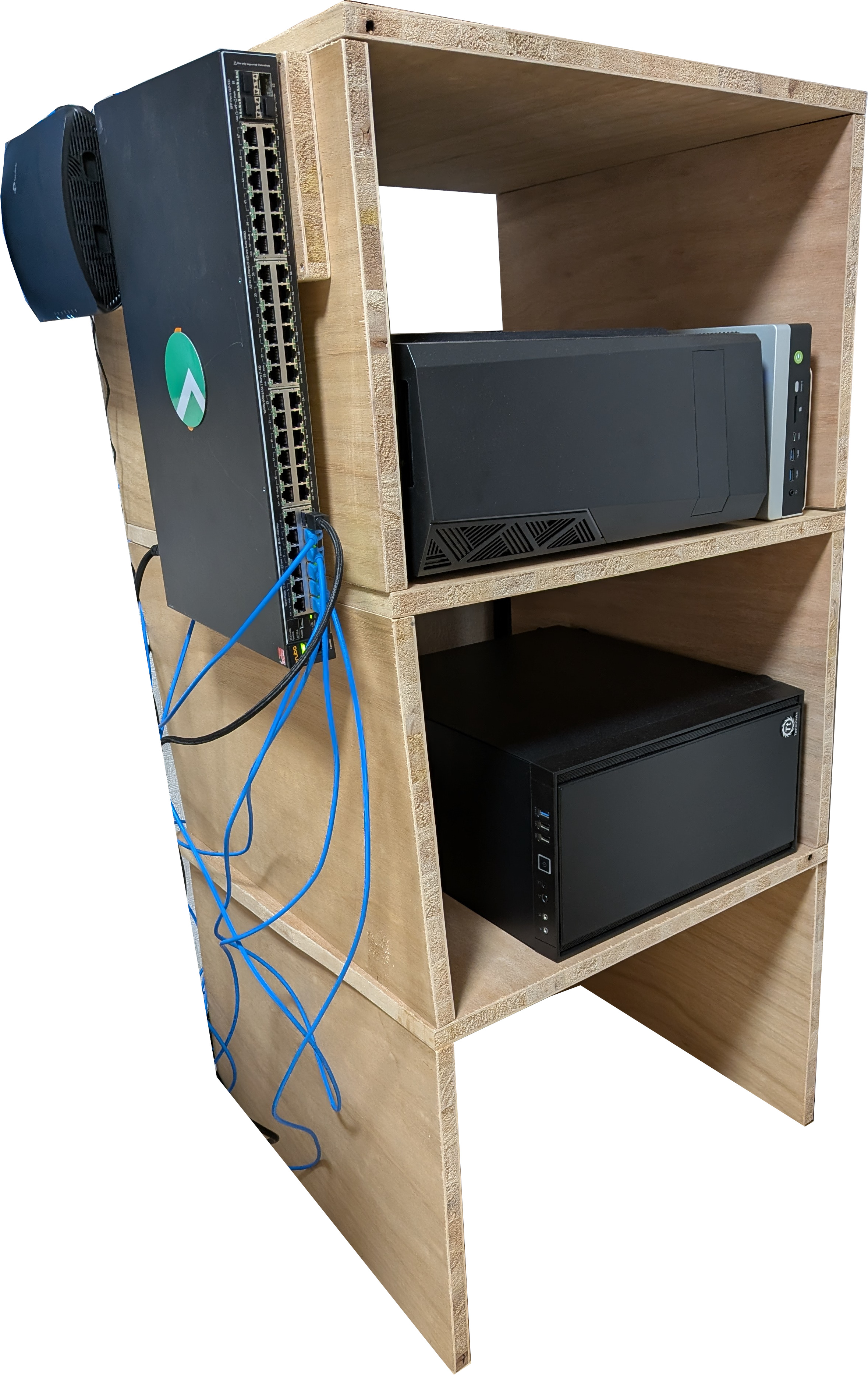
It also has a dedicated side-extension plate that lets me mount an HP Aruba network switch vertically.
Design Specifications
| Spec | Value |
|---|---|
| Modular Concept | Each layer is a U-shaped “cradle” that stacks on top of the previous one |
| Per-Layer Dimensions | 58cm (Width) x 57cm (Depth) x 40cm (Height) |
| Case Clearance | Accommodates large PC cases, with room for optical drive ejection and cable management |
| Access | The back is completely open for easy cabling |
| Stability | Free-standing design; place on a level, solid floor and avoid overloading a single layer |
| Switch Mount | Dedicated side-extension for network switches, mounted vertically |
Materials List
Assuming 3 layers. Multiply the “per layer” items if you want more.
Wood (20mm Thick Plywood Recommended)
| Piece | Dimensions (cm) | Quantity | Purpose |
|---|---|---|---|
| Base Plate | 58 x 57 | 3 | Floor of each PC layer |
| Side Wall | 38 x 57 | 6 | Sides of each PC layer |
| Switch Plate | 48 x 15 | 1 | Side mount for the network switch |
Hardware
| Item | Specification | Quantity | Purpose |
|---|---|---|---|
| Wood Screws | 4.0mm x 50mm | ~50 | General assembly |
| Bolts & Nuts | M6 x 40mm | 12 sets | Modular stacking, so you can disassemble without stripping wood |
| Switch Mounting Screws | M4 x 10mm machine screws | 2 | Securing the switch vertically to the switch plate |
| Wood Glue | 1 bottle | Joining side walls to base plates | |
| Sandpaper | 120 grit | 1 sheet | Edge finishing |
Tools Needed
- Circular saw or jigsaw (for cutting the plywood)
- Power drill & drill bits (3.5mm for pilot holes, 6.5mm for M6 bolt clearance holes)
- Measuring tape & square ruler
- Level
- Clamps
- Screwdriver / hex key
Cut List
| Piece | Dimensions (cm) | Quantity |
|---|---|---|
| Bases | 58 x 57 | 3 |
| Sides | 38 x 57 | 6 |
| Switch Mount | 48 x 15 | 1 |
The Build
Step 1: Cutting the Wood
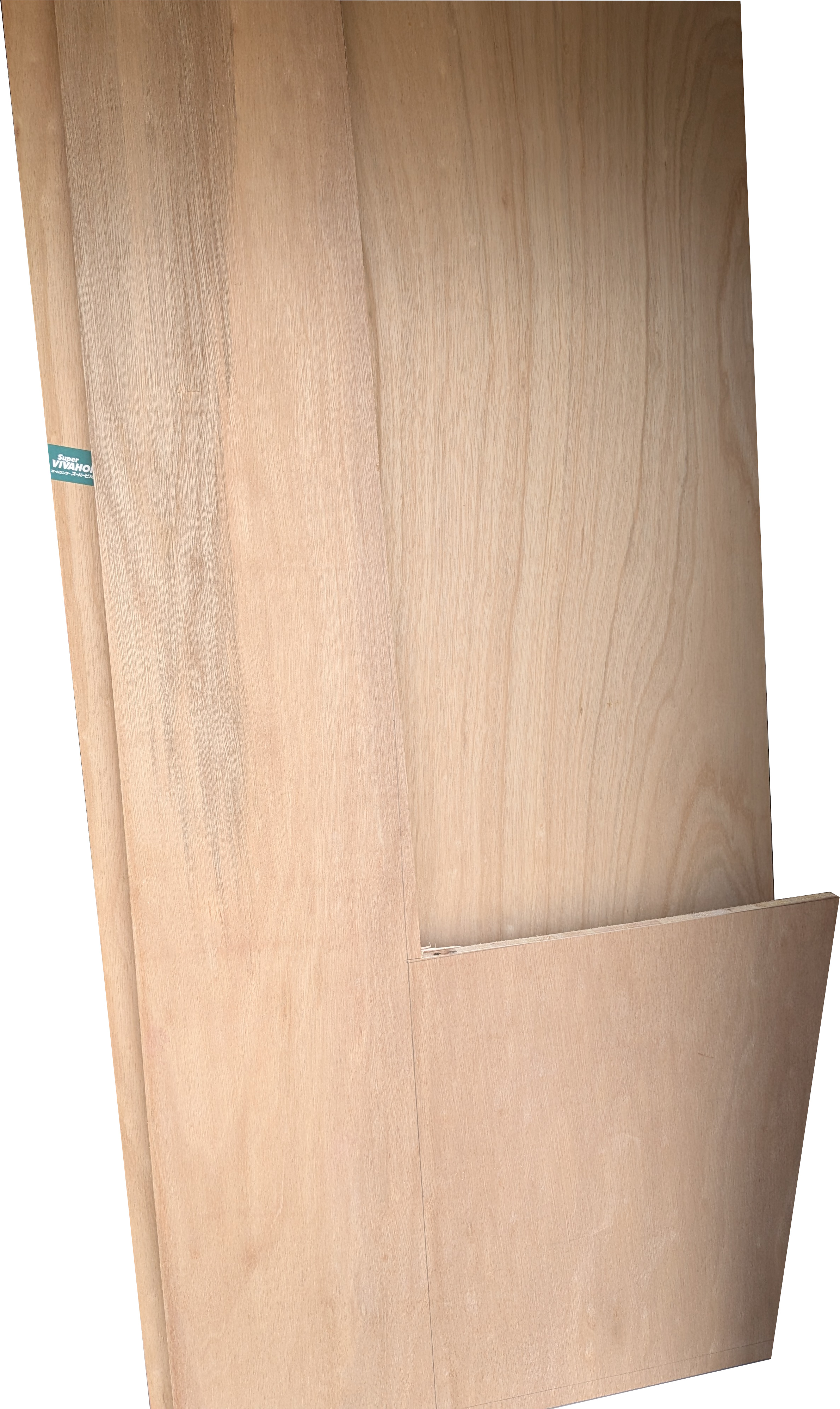
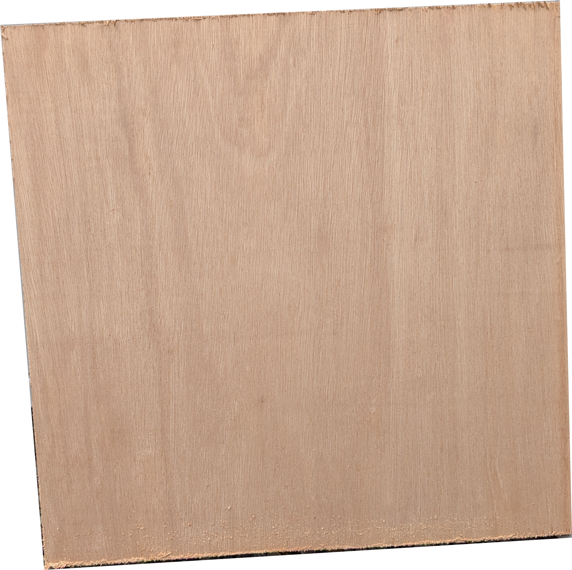
Cut all the plywood pieces according to the cut list. This is the part where the photos are, because I like watching a panel of plywood become something with a purpose:
Once everything is cut:
- Sand all edges with the 120-grit sandpaper to prevent splinters.
- Pre-drill pilot holes for all wood screws to prevent the plywood from splitting. Use a 3.5mm drill bit for all 4.0mm wood screw pilot holes.
Step 2: Building the Modules
Repeat these steps for each layer.
- Lay one Base Plate (58x57) flat.
- Apply wood glue to the bottom edge of the Side Walls (38x57).
- Position the Side Walls on the depth edges (the 57cm edges) of the Base Plate, leaving the 58cm width edges open (front and back).
- Secure each Side Wall with 4 wood screws (4.0x50mm) driven from the bottom of the base into the side wall:
- Drill pilot holes from the underside of the Base Plate: use a 3.5mm drill bit, drill to 30mm depth (20mm through the base plate as clearance + 10mm into the side wall as the pilot). The screw will grip through the remaining ~30mm of the side wall.
- Ensure the sides are perfectly square using your square ruler.
After this step you have three identical U-shaped cradles, each big enough to swallow a large PC case without touching the front or the back.
Step 3: The Modular Stacking System
To make the shelf “slot in” and “take apart” easily, you bolt the base plate of the upper module through the side walls of the lower module. No special drill bits are needed — just the same 6.5mm bit for clearance holes.
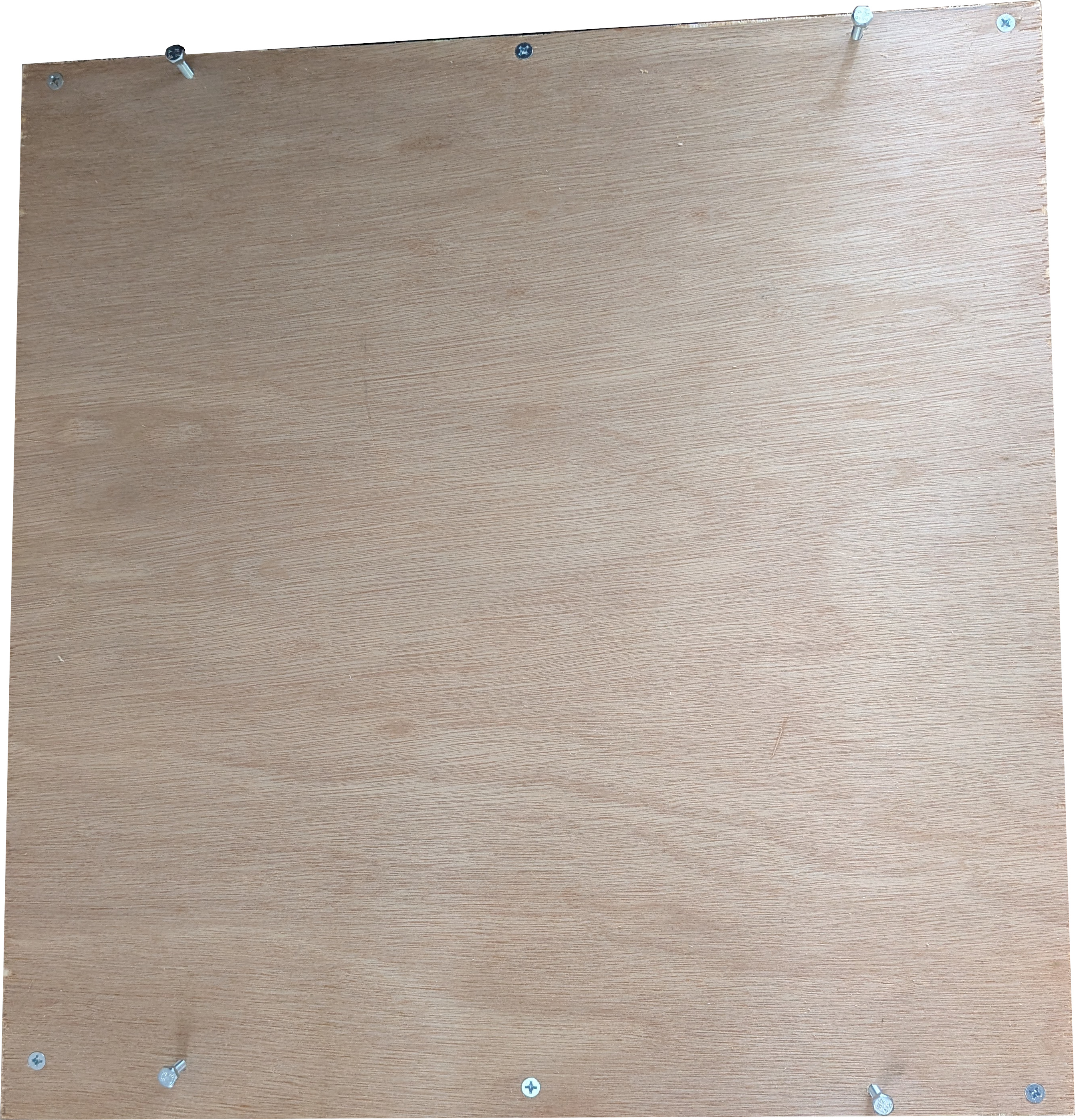
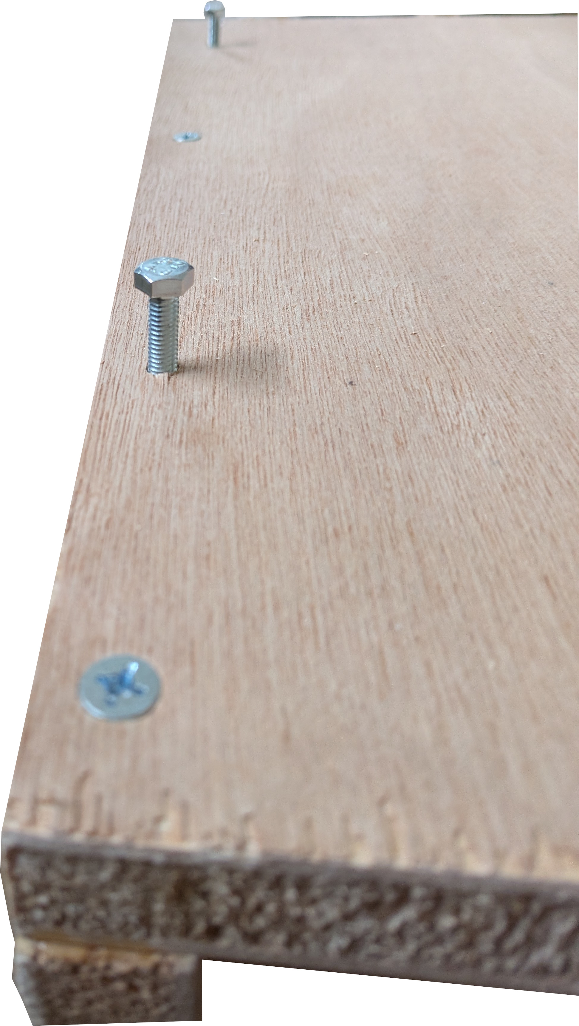
- On the top edge of each side wall of the bottom module (2 positions per side wall, 4 total), drill a 6.5mm clearance hole straight down through the 20mm thickness of the side wall. Space the two holes per side wall evenly along the length (e.g., ~10cm from each end of the 57cm edge).
- On the Base Plate of the next module, mark the four corresponding positions. Drill 6.5mm clearance holes straight through the 20mm thickness at each mark.
- Place the next module on top so the holes align. Insert an M6 x 40mm bolt from below through the base plate hole and into the side wall hole. The bolt head sits on the underside of the base plate, and the bolt protrudes ~20mm into the interior of the lower module’s side wall.
- Thread an M6 nut onto the bolt on the inside face of the side wall, tightening it against the inner surface. The nut clamps the base plate down onto the side wall.
- Repeat for all four bolt positions. Repeat the whole process between Module 2 and Module 3.
The bolt-and-nut system lets you fully disassemble the stack at any time without damaging the wood. Twelve sets of M6 x 40mm for a three-layer shelf — four per joint, two joints.
Step 4: Attaching the Switch Mount
- Take the Switch Plate (48x15).
- Screw it perpendicularly to the outer face of the side wall on the bottom-most module.
- Use 4 wood screws (4.0x50mm) to ensure the plate is flush and secure:
- Drill pilot holes from the Switch Plate into the Side Wall: use a 3.5mm drill bit, drill to 30mm depth (15mm through the switch plate as clearance + 15mm into the side wall as the pilot).
- Position the switch vertically on the switch plate, aligning the rack-ear mounting holes.
- Pre-drill two clearance holes through the switch plate: use a 3.5mm drill bit straight through the 15mm thickness of the plate.
- Secure the switch with 2x M4 x 10mm machine screws through the plate into the rack ears.
I did this for both of my switches, so they sit side-by-side on the bottom layer’s side plate — handy to reach, out of the way, and exactly where the cabling wants them.
Step 5: Final Positioning
- Position the completed shelf against a wall or in your desired location.
- Ensure the shelf sits flat and level on the floor. Use a level to check.
- NOTE: Each layer can exceed 20kg with heavy PC components. Place the shelf on a solid, level floor and avoid locations prone to bumps or impacts.
Visual Diagrams
Module Construction (Top View)
       58 cm
+-------------------+
|      BACK (Open)  |
|                   |
| [Side]     [Side] | 57 cm
|  Wall       Wall  |
|                   |
+-------------------+
       FRONT
Layer Assembly (Side View)
      Side Wall (38cm)
      |  |
      V  V
+-----+-----+  <-- Module 2
|     |     |
+-----+-----+  <-- Module 1
|     |     |
+-----+-----+  <-- Base
       ^
       |
   Floor
Full Stack Concept
   ___________________
  |     PC Layer 3    |
  |___________________|
  |     PC Layer 2    |
  |___________________|
  |     PC Layer 1    | [Switch Mount]
  |___________________|
The Finished Product
The PCs are stacked on their layers, with my two network switches mounted vertically on the side. The open back means every cable runs clean, and when something needs to come out of the stack, I undo four nuts, lift a layer off, and I’m back at the machine in under a minute.
If you’ve been following the woodworking side of this blog, this one started as an idea I ran through a local model — see Using AI for Woodworking on the EVO-X-2 for how I use a local LLM to help plan builds. But the cutting, the drilling, and the swearing at wobbly plywood were all mine.